Español
Design Assistance
Framework for ground improvement design
Design targets
Design for Ground Improvement begins with a definition of the design goals, i.e. the permissible values for:
- Total and differential static settlements
- Dynamic settlements due to soil liquefaction (earthquake)
- Shear strength requirements (bearing capacity, slope stability, lateral spreading)
- Time-settlement requirements (vertical drains, stone columns)
- Water permeability after compaction
- Degree of disturbance to neighboring structures
- Time schedule constraints
The selection of the safest and most cost efficient ground improvement method depends on the above design goals. Eqally important are local soil conditions as determined from soil exploration. The soil exploration shall be custom tailored to find the best ground improvement method.
After selection of the ground improvement method, the designer should also be involved in setting up the Technical Specifications and in the Quality Control measures during execution of the works.
Gathering information for design
The following check list is useful when preparing the necessary information for ground improvement design. If all this information was available, the designer would most likely not have any further questions during the design phase. All this information is rarely ever available. The experienced designer has to make intelligent assumptions and prepare a design that can live with the uncertainties produced by the incomplete information. This is the art of ground improvement design. It requires many years of experience.
- Loads
- Width and length of load bearing elements (footings, rafts, walls)
- Cross sections and layout drawings of structures, wherever available, to identify the relevant cross section or detect stability issues.
- Depth of groundwater table.
- Depth of foundation level below existing ground,
- Planned addition or removal of earth fill, if any. Earth is heavy and sometimes more heavy than the actual building. If we forget this, the settlement estimates can be far off the mark.
- Soil stiffness profile (SPT, CPT, pressuremeter, boreholes), favorably showing on a layout drawing WHERE these soundings are in relation to the foundations under 2) above.
- For settlement in soft clay and silt: Oedometer load and time settlement curves to evaluate soil settlement not only in their magnitude but also in time. Good laboratory data gives more confidence in the calculation assumptions than if we have to correlate soil stiffness from SPT or CPT alone)
- Allowed time for construction (to evaluate the need for vertical drains, vaccum)
- For projects where slope stability is an issue: Friction angle or undrained shear strength over depth from vane shear, CPT correlation, or lab shear tests.
- For projects involving mitigation of earthquake induced settlements and lateral spreading: Moment Magnitude Mw of the earthquake and the Peak Ground Acceleration (PGA) , the water table elevation and for lateral spreading evaluation the relevant cross sections for lateral spreading.
Design for static settlements
The experienced stone column designer starts with a soil mechanical model of the foundation and the soil. Starting from this, a first estimate of necessary stone column grid spacings and column diameters in function of load, soil type and depth is made.
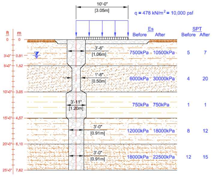
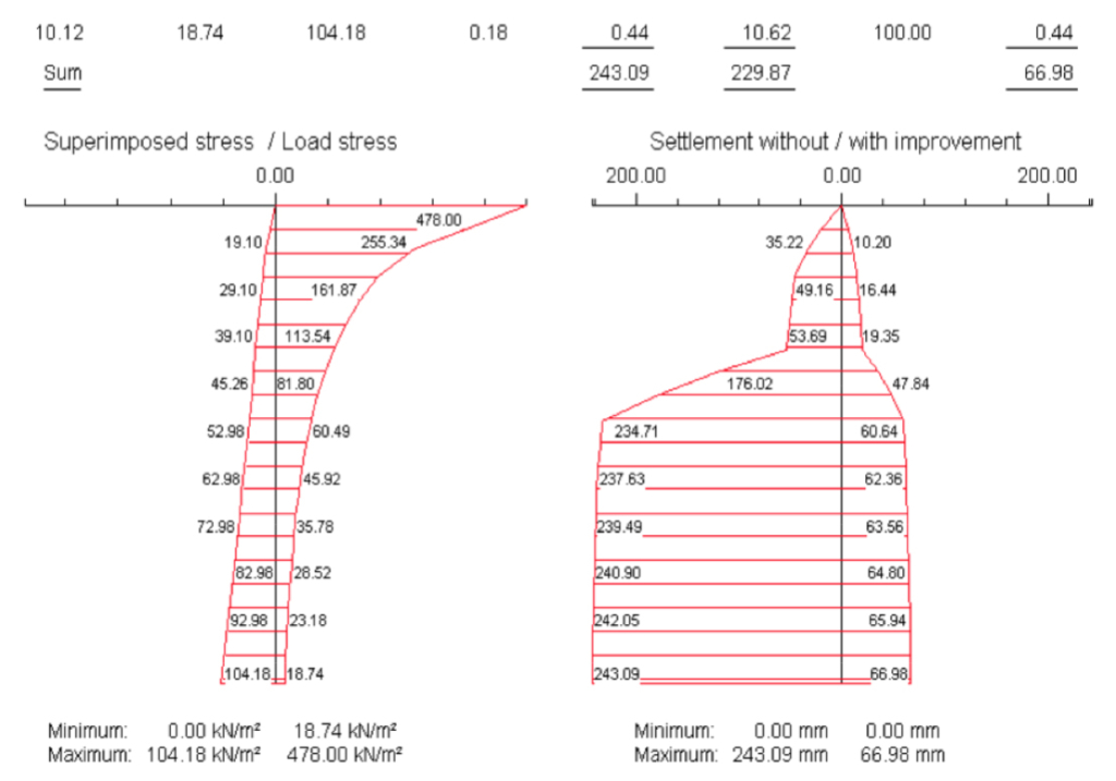
The above soil mechanical model can be entered into the program DC-Vibro of DC-Software GmbH as follows.
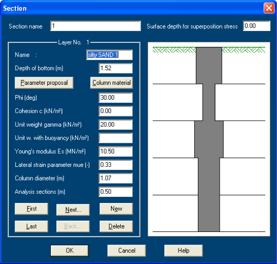
After input of soil parameters, column geometry and grid spacing, the program shows in an overview the input data.
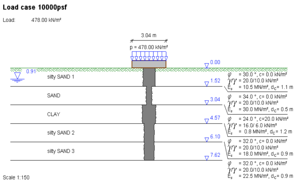
Then it calculates the resulting settlements with and without treatment.
In the below case settlements could be reduced from 243 mm without treatment to only 67 mm with treatment.
Stone columns should have a larger diameter in weaker soil layers than in stronger ones. This will not only produce better overall settlement reduction but also reduce the percentage of such total settlements that would end up being differential settlements. A similarly large reduction in differential settlements is not achieved by designers that design constant diameter columns.
Design using finite element methods
Stone Columns are best modeled with 3-dimensional simulation software, as the load bearing mechanisms between columns are evolving in a 3-dimensional way that does not easily lend itself always to a simplification in 2D.
The following output shows a load test simulated with such a 3D program (Plaxis3D).
It shows a footing with a group of stone columns at failure level. The outer columns are deforming more than the core columns and do this in a non-symmetrical way, away from the center of the footing.
Such deformation behavior cannot be predicted by simpler programs like DC-Vibro. However, as long as stresses stay safely below the failure level, such sideways deformation components are limited and the assumptions of DC-Vibro after Priebe are sufficient for the task of static settlement estimations.
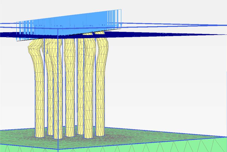
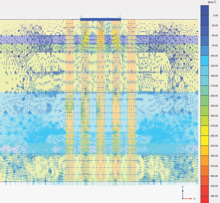
If a very well instrumented load test shall be back-calculated, a 3D Finite Element or Finite Difference simulation is most certainly the method to apply. Below a cross section through a 3D-model of a 5 m x 5 m load test plate is shown.The stress concentration into the columns in the soft (purple) layer is clearly visible as yellow to red lines.
Betterground Engineers utilize such software daily on projects around the world. This provides an advantage in experience both in soil modeling and computer simulation. In the end, however, it will aways be good engineering judgment based on many years of experience that influences the design decisions more than even the best simulations.