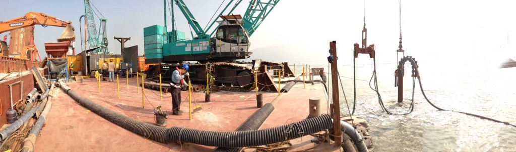
Marine Bottom Feed Stone Columns with custom built pneumatic gravel transport system
Pressure Chamber Injection System
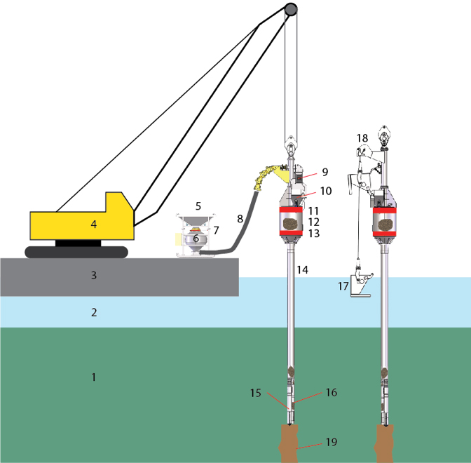
The PCIS (Pressure Chamber Injection System) is the newest evolution of our marine bottom feed stone column installation equipment. In this system a tank (6) is used to blow the stones through a hose (8) instead of the classical way of using a bucket (17). In an offshore application the filling of such bucket (17) would be a challenge as compared to the same operation on land.
A special feature of all Betterground rigs, both with pneumatic system and bucket, are their design around the center of gravity axis. This design allows the rig to penetrate the soil more vertically than rigs which have not been built with the same rigorous approach.
Key to the high quality installation capability of the PCIS is the airtight gate (red) on top of the receiver tank. This gate locks the gravel from atmospheric pressure and puts it under an over-pressure that ranges between 2 to 6 bars . The pressure is dependent on the operating depth of the rig.
Under the applied excess air pressure in the interconnected chamber consisting of receiver tank (12), silo tube (14) and tremie pipe (16), gravel is injected into the soil at the tip of the tremie pipe near the vibroprobe’s nose, hence the name “pressure chamber injection system”. Compared with older Single Large Tank systems, the advantage of the PCIS is that below the gate there is always exactly ONE full batch of gravel filled in with each opening of the airtight gate. This not only allows for less number of open-close cycles of this gate, but also for an as exact as possible recording of gravel batches placed in the ground at defined depths.
Detailed description of gravel transport
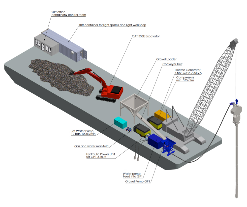
The flow of gravel within our Pressure Chamber Injection System (PCIS) starts with the filling of the hopper (5) with gravel by means of a conveyor belt or an excavator.
From hopper (5) a defined volume of gravel falls into blow tank (6). After gate (7) has closed this gravel volume is pumped by an air stream (compressor not shown here) through the 6-inch hose (8) into the receiver funnel (10) for where it falls through the open gate (11) into the receiver tank (12). During this blow cycle that typically takes 20 seconds to 60 seconds, the lower receiver tank gate (13) is closed, such that in the lower compartment of the rig, the so-called silo tube (14) a constant airflow can be maintained at all times. The total gravel storage volume under gate (13) is at least as large as the gravel storage volume in the receiver tank (12) and the blow tank (6), so that a batch of gravel can travel through these three stations without overfilling in the next station down the line.
From the silo tube the gravel flows without any restrictions into the stone extraction channel (16) and from there to the tip of the vibroprobe (15). There the gravel is ultimately displaced into the soil by up and down movement of the vibroflot. The installation of the column itself is described in detail in chapter 3.4.
Barge setup
Low Headroom Marine Bottom Feed Stone Column rig SB1
The custom built low headroom marine bottom feed stone column rig SB1 uses the same gravel transport unit GP1 but has completely different attachment to the vibroflot.
To minimize lost penetration length the locks are not built around a bulky receiver tank like in a standard rig, but moved into the silo tube (12).
This saves about 7 m to 9 m on the otherwise non-usable length in the upper part of the rig.
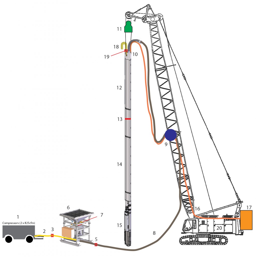
The gravel is filled into hopper (6) and falls from there through knife-gate (7) into the blow tank (4) that has a defined volume of 1 m3. Once the blow tank is completely filled and the knife-gate (7) has closed, valves (3), (5) and (19) open and air is blown from compressor(s) (1) through air hose(s) (2) into the lower part of blow tank (4). On the other end of the lower part of the blow tank, the air, now mixed with gravel, exits through the 6-inch stone transport hose (8) an is transported via the hose basket (9) to the receiver (10). From the receiver (10) the gravel falls in the upper silo tube (12) that is at that time (during the gravel blowing cycle) isolated from the lower silo tube (14) by an internal lock (13) that is here only shown schematically. The excess air from the gravel blowing process is expelled through one or two exhaust outlets (yellow, 18). These can be locked by valve(s) (19), which are open during the gravel blowing cycle.
After the blowing of one batch is completed, valves (3), (5) and (19) close, so that the upper silo tube is now closed off against the atmosphere. Once a level sensor inside the lower silo tube (14) shows empty, the internal lock (13) opens and the batch of gravel falls from the upper silo tube (12) into the lower silo tube (14). Since the stone transport hose (8) and the exhaust outlet(s) (18) are closed by valves (5) and (19) respectively, the two silo tubes (12) and (14) that are now connected through the open lock (13) are both under the required excess air pressure that is demanded in the Specs and that is necessary to expel the gravel at the tip of the vibroflot (15) through the mud protection nose cone.