Betterground quality monitoring and control system
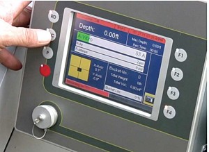
The quality control recorder is a touchscreen unit located in the rig operator cabin.
The unit can act as a remote control for regulating the pressure or flow of water, air, or even cement grout. This regulation can be programmed to follow an automatic or semi-automatic rule where these flows are regulated depending on depth level.
Operator guidance system
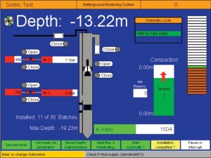
The software guides the operator to install a specified column diameter or achieve the necessary ampere layer by layer as required.
This is accomplished by the green bar graph on the right of the display (titled “Compaction”). As the operator moves the Vibroflot up and down to install the column, this green bar empties or fills and at both ends the red arrow reverses direction to indicate to the operator to also reverse direction from, say, upward movement to downward movement.
The bar on the far right shows in orange the already installed column, green the present depth interval, and white the remaining intervals till completion of this column.
The valve controllers for the various air lock chambers of the Pressured Chamber Injection System rig are shown in the left part of the display, indicating status of the valve, flow rate and pressure.
At the bottom of the screen a row of buttons (green, last one yellow) shows the present position of the control computer in the process of installing an offshore stone column. The operator works sequentially from the leftmost to the rightmost button during the installation process, with the presently available selection in Yellow and the already completed steps Green.
This way most operators learn to run the system error free without ever needing a manual.
Stone Column Monitoring Printout
The following shows a typical printout for a bottom feed stone column installed with constant diameter.
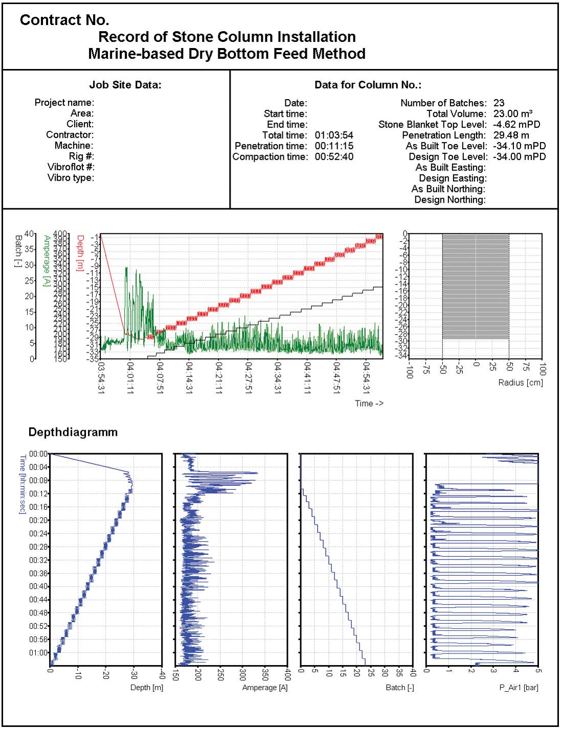
The following parameters are read and stored every second during stone column installation:
- Depth
- Amperage
- Air pressure in double lock system
- Inclination
The recorder can be connected to sensors for
- Depth (with deflection rollers or laser)
- Hydraulic pressure (crowd force)
- Concrete, grout or water pressure
- Flow rate
- Inclination of mast in x- and y- direction
- Frequency measurement at the vibroprobe
- The output can be analyzed in a custom made software or in Excel. Seen below, a magnified plot was created to better study the build up of Ampere during rig penetration and subsequent column installation.

Specifying Quality Control for Stone Columns
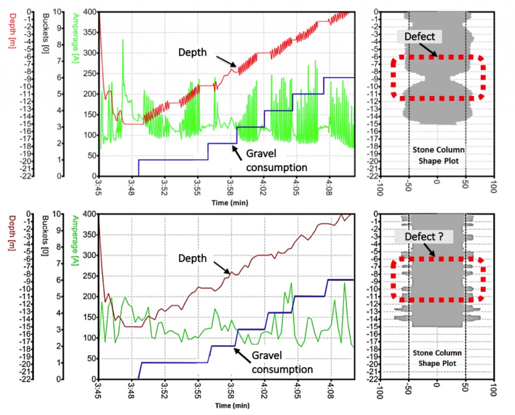
The below two graphs show the identical stone column point that exhibits an installation error at around 8 m to 10 m depth. In that range the
operator has not moved the rig often enough up and down, therefore releasing only minimal amount of gravel in that depth interval.
In the first plot (1 second recording interval) this is clearly visible, while in the second plot (where 19 out of 20 readings have been removed to simulate
a data logging interval of 20 seconds) this error is not visible at all.
It is therefore not enough to specify “continuous recording of Ampere, Depth, Time and placed Gravel Volume over Depth”, the interval of such recordings
must also be specified.